RCJ 2024 - Záchranár - Skolska Knjiga CRO Team
(ak ste prihlásení, stlačte "Upraviť" a skopírujte obsah tejto stránky na svoju stránku - okrem tohto riadku - a potom ju upravte)
naspäť na zoznam tímov RCJ 2024
Skolska Knjiga CRO Team
School/Club:Hrvatski Robotički savez
Contact: ivan.perko007@gmail.com , borut.patcev@gmail.com
Category: Rescue Line
Previous history of the model
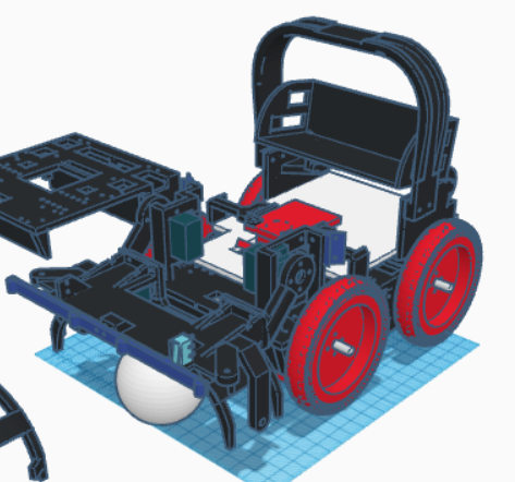
We are the Školska knjiga Cro Team and this year we are competing in the Rescue Line category. We made a completely new robot design this year. The robot is comprised of a 3D printed chassis, wheels, the handle, victim basket, and hand with grippers, our custom designed printed circuit board (PCB), Teensy 4.1 and different electronic components such as motors, infrared sensors, cameras, compass, servos, motor drivers and power supply. The 3D printed chassis, victim basket and hand were designed part in Solidworks and part in Tinkercad. The simpler parts like wheels and the handle were designed in Tinkercad because it’s easier to use and the more complicated parts like the chassis, hand and basket were designed in Solidworks because it’s more professional. The printed circuit board was designed in EasyEDA. The wheels are made with a custom silicon solution and the front wheels have triangle shaped holes carved out the silicon for added grip. Our robot was designed to cover all the aspects of Rescue line and solve them without problems.
Construction and Hardware
1. Chassis: The robot is set on a 180mm × 120mm × 3mm 3D printed chassis which was printed on a Bambu Lab P1S. At the bottom of the robot are 4x 250:1 12V Pololu Motors of which only the 2 front motors have encoders, a 2300mAh 11.1V Tattu battery, 2 LEDs, a OpenMV H7 camera which is pointed downwards at a 45-degree angle which we found had the best lightning and intersection detection and of course the Line following PCB.
2. Hand with Grippers, photodiode and Pushbuttons: The hand and the grippers were both designed in Solidworks and the hand is moved around by 2 270-degree servo motors, and the grippers are moved by 2 180-degree servos to grab the victims. On the robot we have 4 pushbuttons and all of them are placed on the hand. They are used to detect the evacuation point and the walls in the evacuation zone. The photodiode is also placed on the hand and is used to detect when there’s a victim in front of the hand. 3. Wheels and Motors: For the motors we chose the 250:1 12V Pololu Motors and we have four of them. They are mounted to the bottom part of the chassis but aren’t screwed directly to the chassis rather to a metal motor holder which is itself screwed to the chassis. We made that to prevent the chassis from breaking under loads because on previous robots that had the motor holder printed together with the chassis, the holder frequently broke and the motors were shaking and couldn’t be tightened and secured properly. As for the wheels we made our custom wheels with a 3D printed chassis and a custom silicone solution. On our wheels there’s something special. The front wheels have triangle shaped holes carved out of the silicon. We did that because our robot would repeatedly get stuck on speedbumps when they were placed on the ramp going up. First we placed the carved out wheels on the rear wheels but that didn’t do much regarding our problem. Only after we placed them on the front wheels did the robot start going up the ramp. Because our speedbumps are held down to the tiles using white tape which has very little traction our robot’s front wheels would always slip and couldn’t catch any grip to go over the speedbumps. When we saw that we carved out holes in our wheels which were approximately the size of a speedbump so the robot could catch the speedbump in any of the gaps and go over it with the front wheels. After the robot passes the speedbumps with the front wheels the rear wheels will have enough traction to go over the speedbumps themselves
Robot parts
➢ 3D printed chassis and hand with grippers ➢ Custom wheels ➢ Custom PCB ➢ Teensy 4.1 ➢ Voltage Regulator(5V and 3.3V) ➢ Motor Driver ➢ 1x OpenMV H7+ Camera ➢ IMU (compass, accelerometer, gyroscope) ➢ 5x LIDAR Distance Sensors ➢ 11x IR Line Sensors ➢ 4x 250:1 12V Pololu Motors ➢ 2x Pololu Encoder ➢ Tattu 2300 mAh 11.1V Battery ➢ 3x 180° Hobby Servos ➢ 2x 270° Hobby Servos ➢ 5x Pushbuttons ➢ 3x LEDs ➢ Photodiode
3D models, drawings, construction schematics, and part blueprints
The robot was designed in Solidworks and Tinkercad 3D modeling programs.

Schematics, PCB designs, electronics
The PCB was made in the EasyEDA program
Software
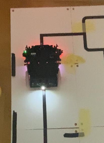
===Since our main controller is Teensy 4.1 the programming language we use is Arduino C++ and OpenMV software(micropython). The program itself consists of the main program and seven subprograms. The program is divided into two main parts: Line following (including obstacle detection, green square detection and PID algorithm) and Evacuation zone (victim detection, rescuing the victims, exit bonus). The line following goes as such: when the robot is turned on and two pushbuttons on the hand are pressed the robot starts calibrating. When the pushbutton on the handle is pressed, the robot’s program starts. Firstly he starts following the line using the PID algorithm. While following the line he is checking for green squares on intersections with the camera, obstacles with the IR distance sensor, ramps with the IMU and the entrance into the evacuation zone with two LIDAR sensors.==
Fotodocumentation
Other
We wish the very best of luck to all teams!
![[1640,1200]náhľad](/images/1/10/Pcb_slik.png)
![[1640, 1200]náhľad](/images/0/08/Prog_2023_cijeli.png)
